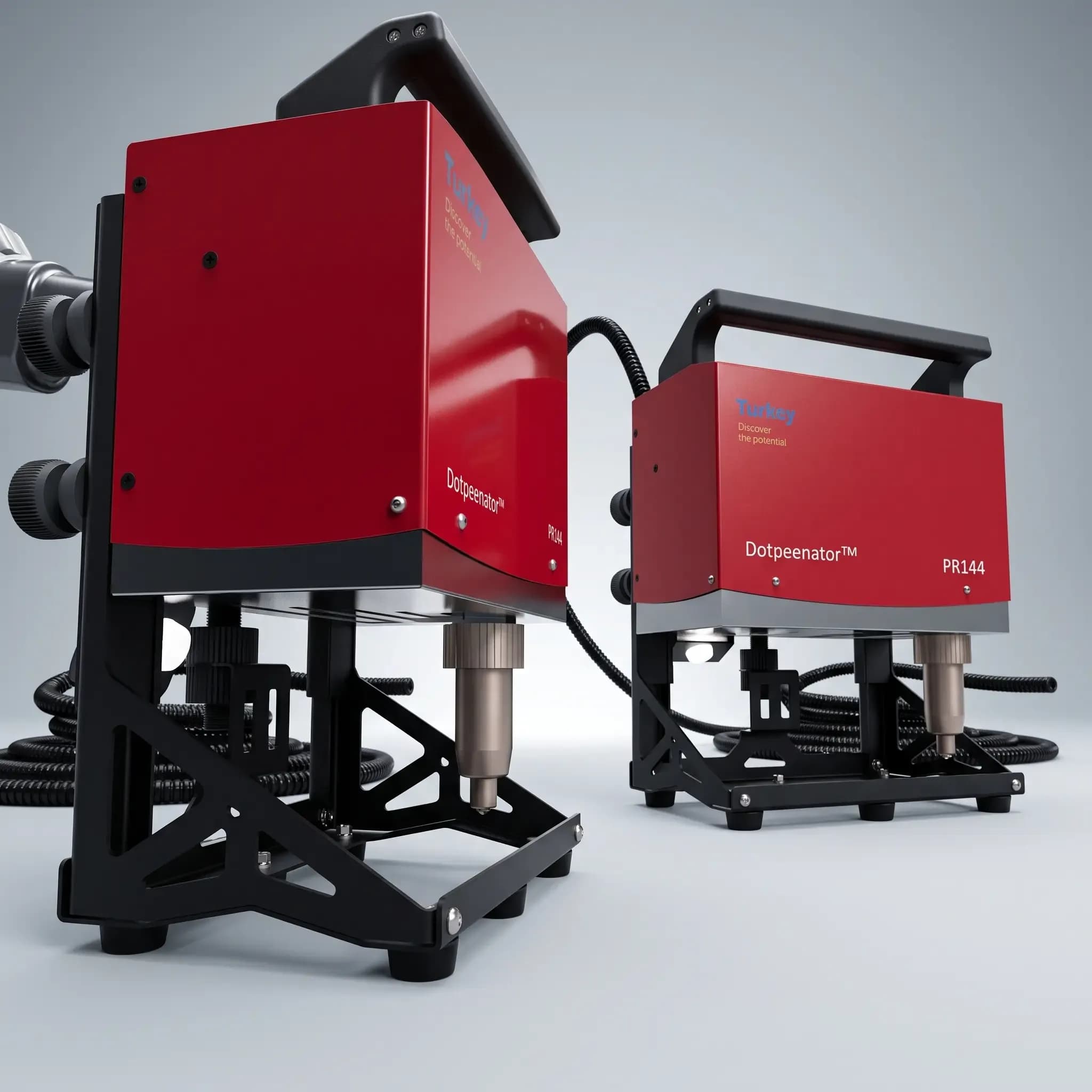
DPM Marking Methods and Types: How Does Each Technology Work?
You can mark the exact same DataMatrix code using five different technologies, but not all five will deliver the same lifespan, durability, or readability on a given part. In this article, we examine the physics, strengths, and limitations of each DPM marking method through the eyes of a quality control engineer.
By Erden Arıkan · Mechatronics Engineer
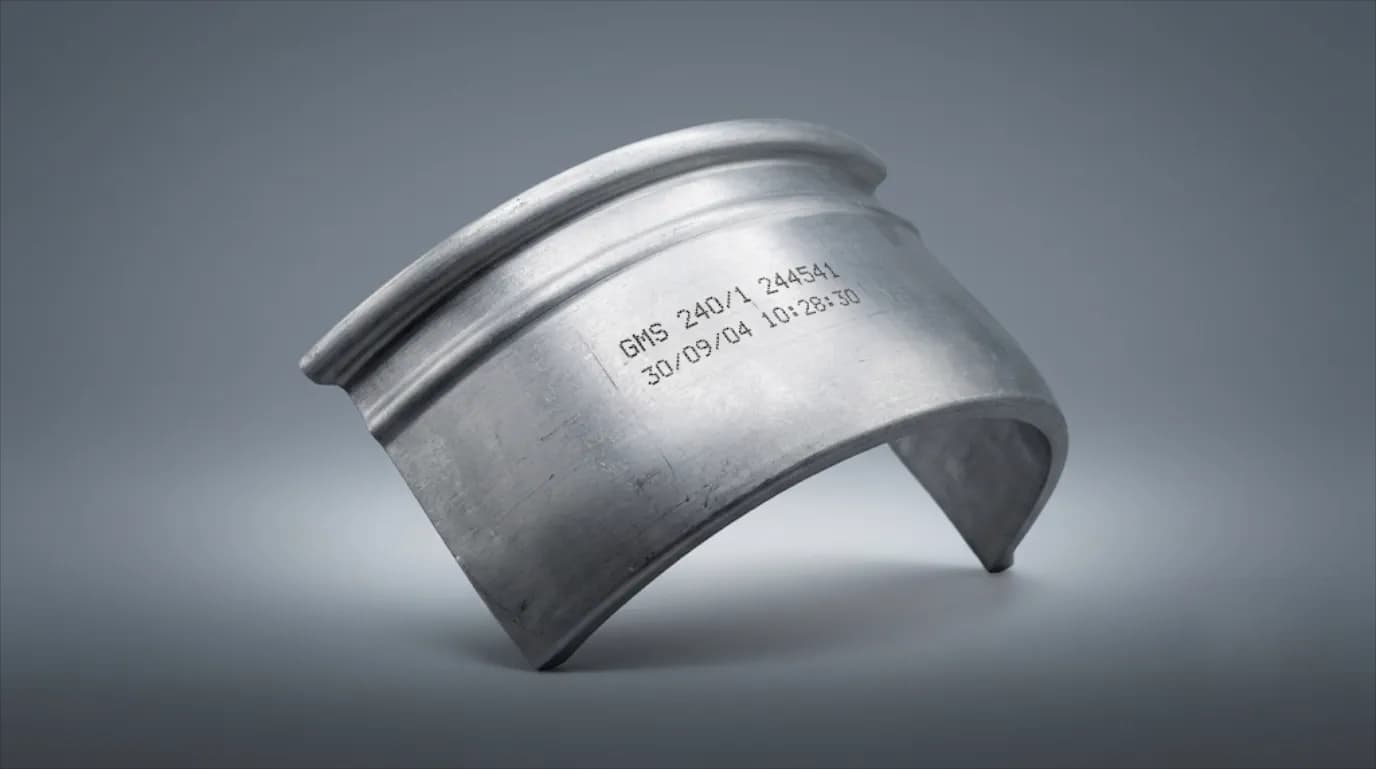
In the first article of this series, we covered What is DPM (Direct Part Marking) and the Fundamentals of Traceability, discussing why marking a code directly onto a part for permanent lifetime tracking differs fundamentally from applying an adhesive label.
The topic of this article addresses the next critical question: how do we mark this code onto the part?
The most frequent mistake we observe in the field is selecting technology based on budget rather than the part's specifications. Marking methods sit at the center of an engineering chain ranging from material hardness and surface finishing to fatigue life and scanner capability. An incorrect choice results in a mark that looks flawless to the naked eye but fails automated verification—or conversely, a mark that reads perfectly but creates stress risers that compromise the mechanical integrity of the component.
Below, we break down each method individually, analyzing its operating principle, strengths, and real-world industrial limitations.
Five Questions to Answer Before Choosing a Method
When evaluating a new application, the first step is not marking a sample; it is answering these five fundamental questions:
- What are the material and its hardness?
Soft aluminum and 60 HRC hardened steel cannot be processed the same way. As material hardness increases, mechanical marking options narrow while laser marking becomes increasingly advantageous.
- What post-marking processes will the part undergo?
Where is the marking station located in the production workflow? Will the part undergo sandblasting, heat treatment, painting, e-coating (cataphoresis), or salt spray testing after marking? Surface-only marks will not survive most of these processes; deep indented marks will.
- Is surface integrity critical?
On dynamic, fatigue-critical components, every notch is a potential crack initiation point. In aerospace and defense applications, mark depth is strictly governed and limited by engineering standards rather than left to chance.
- Who or what will read the code?
A human operator, a handheld scanner, or an inline fixed-mount vision camera? For human-readable serial numbers, the primary criterion is visual clarity; for machine-readable DataMatrix codes, the criteria are contrast, cell geometry, and the ISO/IEC 29158 verification grade.
- What are the cycle time and integration requirements?
A portable handheld unit versus fully automated inline integration represents drastically different operational workflows and investment profiles, even within the exact same marking technology.
Once you have answered these five questions, you will clearly identify the optimal marking method for your application below.
Dot Peen Marking (Micro-Percussion Marking)
How It Works
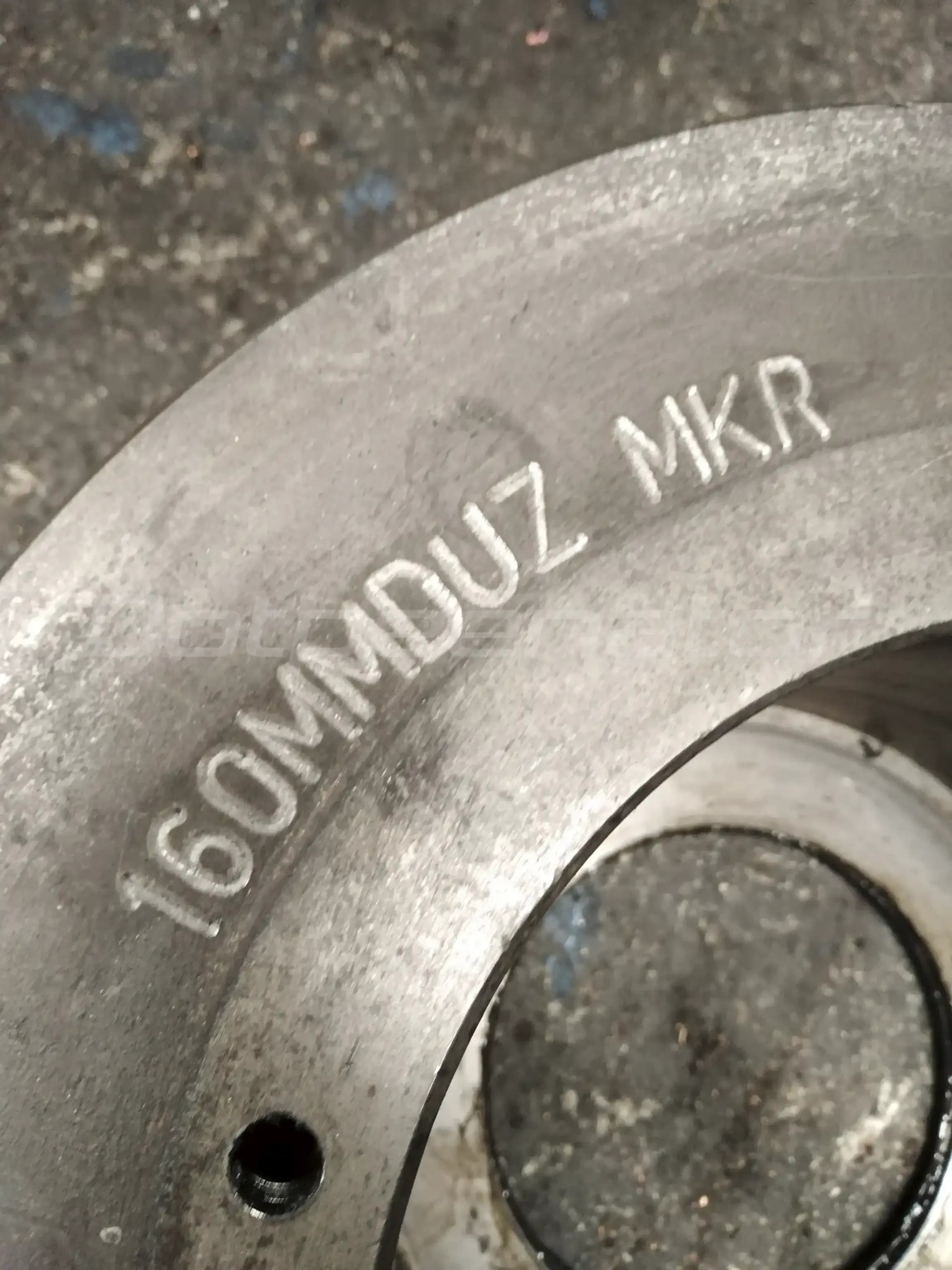
A tungsten carbide stylus is driven at high frequency by pneumatic pressure or an electromagnetic solenoid. As the stylus impacts the material, it does not remove material; it displaces it via plastic deformation. As the marking head moves along the X-Y axes, the controller precisely coordinates each impact point. Alphanumeric characters, logos, and 2D DataMatrix codes are formed from these closely spaced indents.
Key process parameters include:
- Stylus angle: Typically 60°, 90°, or 120°. A narrower angle produces a deeper, smaller dot; a wider angle creates a shallower, broader indent. A 60° stylus is generally preferred for DataMatrix codes.
- Impact force / dwell time: Determines mark depth. Increasing depth enhances visual contrast, but excessive depth can compromise surface integrity and degrade camera readability.
- Dot size / cell ratio: For machine-readable 2D codes, the ratio of dot diameter to grid cell spacing is critical; practically, a 60%–75% fill ratio delivers optimal read rates. If dots overlap excessively, the code blurs into solid blocks; if they are too small, scanners cannot resolve individual modules.
- Marking speed and pitch: Determines the overall cycle time in characters per second.
Strengths
- Permanent durability. Because the mark penetrates into the base material, it remains readable even after sandblasting, painting, heat treatment, and heavy operational wear. This makes it the standard choice for chassis, engine blocks, shafts, and flanges.
- Material versatility. Operates effectively across aluminum, carbon steel, stainless steel, cast iron, brass, and industrial plastics. Capable of marking materials up to approximately 62 HRC.
- Investment and operating costs. Significantly lower initial capital cost compared to industrial lasers, with minimal consumable expenditure limited to occasional stylus replacement.
- Portability. For oversized parts that cannot be positioned under a fixed workstation (such as heavy equipment chassis, large pipes, pressure vessels, and structural steel), portable dot peen units can be brought directly to the part—a major advantage over stationary laser systems.
- Safety. Since dot peen does not utilize Class 4 laser radiation, it requires no protective optical enclosures, interlocks, or fume extraction systems.
Limitations
- Acoustic noise. As an impact-based mechanical process, noise levels can be noticeable depending on the structural geometry of the part. It is unsuited for quiet office-like environments, though standard in manufacturing workshops.
- Thin or flexible parts. On thin sheet metal, impact forces can cause reverse-side embossing or distortion; parts must be rigidly supported underneath.
- Surface stress. Indentation depth must be strictly monitored in fatigue-critical applications.
- Speed. For dense graphics or high-character-count text strings, it is slower than laser marking.
Typical Applications
Automotive powertrain components (engine blocks, crankshafts, transmission housings, cast parts); heavy machinery and trailer VIN marking; defense component and firearm receiver identification; structural steel billet and profile traceability.
Scribe Marking (Scratch Marking)
How It Works
Often called the "silent sibling" of dot peen. Instead of reciprocating impacts, a tungsten carbide or diamond stylus is continuously driven into the surface under controlled pneumatic pressure. As the marking head moves along the X-Y axes, it draws continuous grooves into the material. The resulting mark consists of smooth, solid continuous lines rather than individual dots.
Strengths
- Significantly reduced operational noise compared to dot peen.
- Produces clean, highly aesthetic, continuous line fonts with superior visual readability.
- Lower dynamic shock and impact stress on delicate assemblies.
Limitations
- Less effective on very hard materials compared to dot peen; best suited for aluminum, brass, plastics, and mild steels.
- Stylus wear can be higher due to continuous friction.
- Less commonly used for cellular 2D DataMatrix codes compared to dot peen.
Typical Applications
Aerospace identification plates and tags, automotive VIN scribing in quiet assembly areas, electrical enclosures, and noise-restricted manufacturing cells.
Laser Marking
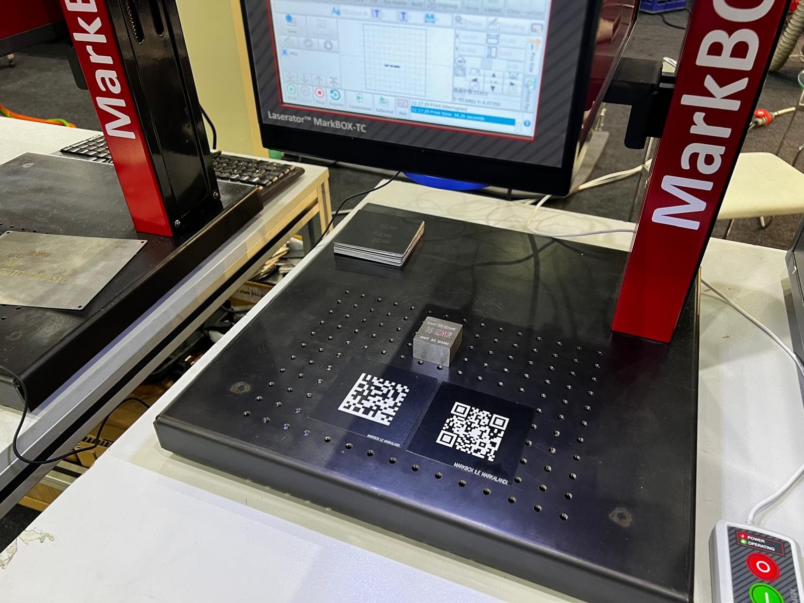
Laser marking is not a single process; it is a family of technologies differentiated by laser source wavelength, pulse architecture, and beam-material interaction. In industrial manufacturing, "laser marking" typically refers to one of five physical interactions:
Mode | Physical Mechanism | Typical Application |
|---|---|---|
Annealing | No material is removed; controlled localized heating induces a subsurface oxide layer resulting in high-contrast dark marks | Stainless steel, titanium, medical instruments (preserves passive corrosion resistance) |
Engraving | Material is vaporized and ablated to create physical depth on the surface | Molds, tooling, high-wear industrial components |
Ablation (coating removal) | Only the top coating/paint layer is removed, revealing the contrasting substrate | Painted surfaces, anodized aluminum, automotive backlit buttons |
Foaming | Localized heat creates micro-bubbles within plastic polymers, resulting in a raised, light-colored mark | Dark engineering plastics, polymer housings |
Color change / Dark marking | Precise pulse-width control produces high-contrast surface oxide coloration | MOPA fiber lasers marking aluminum (black) and stainless steel (color) |
Laser Source Types
- Fiber Laser (1064 nm): The standard industrial solution for metals and many engineering plastics. The most widely deployed source in manufacturing.
- MOPA Fiber Laser: Offers adjustable pulse duration (pulse width), enabling high-contrast black marking on anodized aluminum and precise annealing on stainless steel without surface burning.
- CO₂ Laser (10.6 µm): Designed for organic non-metallic materials—wood, cardboard, glass, and standard plastics. Does not mark bare metals directly.
- UV Laser (355 nm): "Cold marking" technology. Minimizes the Heat Affected Zone (HAZ), making it the prime choice for sensitive medical polymers, white plastics, and electronic components.
Strengths
- Speed. Exceptional cycle times on dense DataMatrix codes, complex graphics, and large text volumes.
- Resolution. Capable of producing microscopic, high-density 2D codes with sub-millimeter cell sizes.
- Non-contact processing. Zero mechanical force applied to the component, preventing mechanical deformation on delicate parts.
- No consumables. Operates without styluses, inks, chemical electrolytes, or mechanical wear items.
Limitations
- Capital investment. Initial machine acquisition costs are noticeably higher than mechanical dot peen systems.
- Safety and infrastructure. Class 4 lasers require light-tight protective enclosures, interlocked safety doors, and active fume extraction/filtration systems.
- Durability variation by mode. An annealed mark may fade or disappear under heavy shot-peening or aggressive sandblasting. The statement "it is marked by laser, therefore it is permanent" depends strictly on the marking mode applied.
- Reflective materials. Highly reflective metals like bare copper and polished brass require optimized wavelengths and parameters.
- Workstation restrictions. The component must generally be positioned inside a laser enclosure, limiting application on massive, immovable structures.
Electrochemical Marking (Electro-Etching)
How It Works
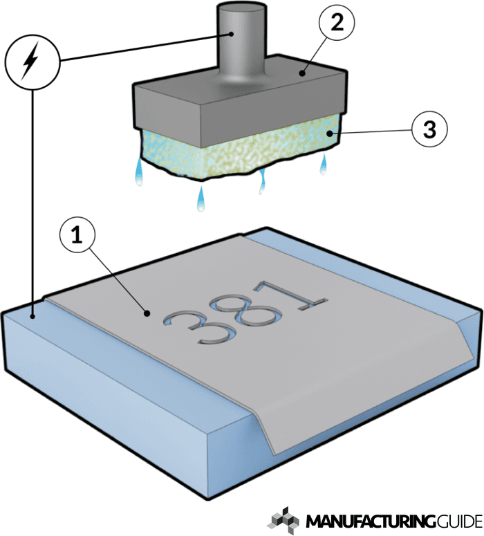
A conductive stencil containing the negative image of the mark is placed on the component. The stencil is saturated with an electrolyte solution, and a low-voltage electrical current is applied via a marking electrode. Direct current (DC) dissolves a micro-layer of material to create a shallow etch, while alternating current (AC) creates a dark, oxidized surface mark.
Strengths
- Very low initial equipment investment.
- Near-zero mechanical stress and minimal thermal input, preserving the surface integrity of hardened or thin precision components.
- Long-established standard in cutlery, precision bearings, and traditional surgical instruments.
Limitations
- Restricted to electrically conductive metals. Cannot mark plastics, ceramics, or non-conductive composites.
- Requires a physical stencil for each layout; impractical for dynamic serialized data (incremental serial numbers, timestamps, lot numbers). This factor alone eliminates it from modern automated traceability lines.
- Slower, predominantly manual operation requiring chemical consumable handling and post-marking neutralization.
Continuous and Thermal Inkjet Coding (CIJ / TIJ)
How It Works
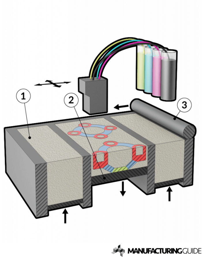
Continuous Inkjet (CIJ) or Thermal Inkjet (TIJ) printheads propel microscopic droplets of ink across an open gap onto the moving product surface. This represents standard packaging coding: printing expiration dates, batch numbers, and shift codes on secondary packaging.
Strengths
- Operates at exceptionally high production line speeds.
- Applies markings across virtually any geometry or packaging substrate.
- Seamless handling of dynamic variable data (real-time timestamps, counters).
Limitations
- Not permanent. Inks can be degraded or washed away by industrial solvents, friction, oils, and chemical degreasing baths. Inkjet is technically a surface-deposition coding method rather than true direct part marking (DPM).
- Ongoing recurring costs for specialized inks and make-up solvents, along with periodic printhead maintenance.
- Unsuitable for multi-year industrial component traceability under harsh operating conditions.
While ideal for FMCG packaging, inkjet is generally unsuited for lifelong industrial traceability. Industrial facilities frequently utilize both inkjet for outer packaging and dot peen or laser for the metallic components inside.
Impact Stamping and Press Marking (Hard Stamping)
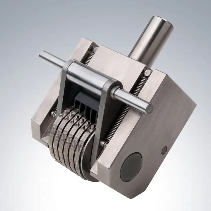
The traditional mechanical method: hardened steel stamp types featuring embossed characters are driven into the metal surface using manual hammer strikes or mechanical/hydraulic presses.
Strengths: Very low initial tooling cost, requires no electrical power, and applies complete character sets in a single mechanical stroke.
Limitations: Variable serialization requires manual, mechanical replacement of individual stamp types. High impact forces induce severe mechanical stress, distortion, and micro-cracking in the workpiece. Mark depth and alignment depend heavily on operator technique, resulting in poor repeatability. Incompatible with 2D DataMatrix symbologies.
Industrial operations requiring automated digital traceability typically replace hard stamping with programmable dot peen systems.
Comparison Table
Criteria | Dot Peen | Scribe | Laser | Electrochemical | Industrial Inkjet |
|---|---|---|---|---|---|
Permanence | Very High | High | Mode-Dependent (High/Medium) | Medium | Low |
Speed | Medium | Medium | High | Low | Very High |
Material Range | Very Broad | Broad (predominantly soft metals) | Very Broad (source-dependent) | Conductive metals only | Very Broad |
Surface Stress | Medium | Low | None (non-contact) | None | None |
Variable Data | Fully automated | Fully automated | Fully automated | Difficult / Manual | Fully automated |
Investment Cost | Low to Moderate | Low to Moderate | High | Very Low | Moderate |
Consumables | Stylus only | Stylus only | None | Electrolyte + Stencils | Inks + Solvents |
Portability | High (Handheld available) | High | Limited | High | Moderate |
Noise Level | High | Low | Low | Silent | Low |
Quick Guide by Material
- Structural steel, cast iron, heavy castings: Dot peen. Exceptional permanence through post-process blasting, e-coating, and heavy painting.
- Hardened steel (>62 HRC): Fiber laser. Mechanical styluses cannot reliably penetrate materials at this hardness level.
- Stainless steel, surgical instruments: Laser annealing. Does not breach the passive oxide layer, preserving corrosion resistance and cleanability.
- Aluminum and light alloys: Dot peen, scribe, or MOPA fiber laser. Selection depends on cosmetic finish requirements and production cycle times.
- Titanium, critical aerospace structures: Laser annealing or depth-controlled dot peen meeting AS9132 specifications.
- Industrial plastics and polymers: UV laser, CO₂ laser, or fiber laser in foaming mode.
- Corrugated packaging, foils, films: Industrial inkjet or CO₂ laser.
Governing Industry Standards
Understanding the compliance standards applicable to your industry eliminates trial-and-error during equipment selection:
- Automotive: AIAG and VDA traceability guidelines, DataMatrix part identification mandates.
- Aerospace and Defense: AS9132 (governing quality criteria, cell geometry, and depth limits for dot peen and laser marking), ATA Spec 2000, MIL-STD-130.
- Medical Devices: FDA UDI and EU MDR regulations requiring permanent direct part identification under GS1 data structures.
- Code Quality and Verification: ISO/IEC 16022 (DataMatrix symbology specification) and ISO/IEC 29158 (AIM DPM) for direct part mark quality assessment.
The final standard is critical: direct part marks must never be evaluated against printed paper barcode metrics (ISO/IEC 15415). DPM codes require specialized multi-angle lighting profiles and dedicated DPM verification equipment according to ISO/IEC 29158.
Frequently Asked Questions
Which DPM method offers the highest permanence? Dot peen and deep laser engraving provide the highest physical durability. Both physically displace or vaporize material below the substrate surface, allowing marks to survive shot-blasting, galvanizing, heavy paint coatings, and mechanical friction. Laser annealing, while durable, remains near the surface and will not survive abrasive blasting.
Should I choose dot peen or laser marking? If the parts are oversized, immovable, budget is constrained, and the data consists of alphanumeric text and standard-sized DataMatrix codes, dot peen is the optimal choice. If the material is hardened (>62 HRC), cycle time is ultra-short, code density is high on small surface areas, or the process must be completely non-contact, choose laser marking.
What is the difference between marking and coding? In industrial engineering, coding generally refers to applying non-permanent batch, lot, or expiry data onto commercial packaging (typically via inkjet). Marking denotes creating permanent, irreversible direct part identification (DPM) onto the component itself for lifelong traceability.
Does dot peen marking weaken mechanical components? When mark depth is properly regulated and positioned away from fatigue-critical stress concentrations, dot peen creates no practical structural weakening. In fatigue-critical aerospace or structural applications, mark depth and location must strictly adhere to engineering drawings and applicable standards (e.g., AS9132).
Which method ensures the best DataMatrix verification grades? For code sizes 8 mm and larger on standard machined surfaces, dot peen delivers excellent verification results. For micro-codes or high-density module arrays, laser marking provides superior edge definition. In both cases, the decisive factors are proper dot/module geometry, adequate surface contrast, and matching lighting geometry on the barcode reader.
Which Method Fits Your Production Line?
You do not have to make this engineering decision in isolation. Send us your sample components; we will mark them in our application laboratory and provide full verification reports alongside optimal process parameters. Prior to committing capital to a production line, validating the exact marking result on your specific material is the safest engineering path forward.